R
Rösti
Unconfirmed Member
On March 5, 2014, Nintendo Co., Ltd. filed in the US a patent application for "Eye Tracking Enabling 3D Viewing on Conventional 2D Display ". It was published today, on July 3, via the USPTO. Inventors are Howard Cheng (manager, Nintendo Technology Development) and William C Newman, JR. (I do not know relation with Nintendo). For a patent it's surprisingly forward and deals with eye tracking, mainly via 3D glasses, and how this can enhance gameplay. As it's not that lengthy, I take the liberty of posting the majority of the text. I have bolded interestings parts.
Inventors: CHENG; Howard; (Sammamish, WA) ; NEWMAN, JR.; William C.; (Redmond, WA)
Applicant: Nintendo Co., Ltd., Kyoto, JP
Assignee: Nintendo Co., Ltd., Kyoto, JP
Family ID: 1000000473577
Appl. No.: 14/197831
Filed: March 5, 2014
Abstract
The exemplary illustrative non-limiting technology herein enables 3D viewing on conventional 2D displays such as home television sets by tracking a person's viewpoint. Detecting a player's viewpoint movement to change the viewing of the displayed object gives the illusion that the object is physically present in three-dimensional space. Viewpoint movement detection can provide collision-related game logic benefits such as allowing a player to dodge projectiles, giving a game character an ability to "see" the player when not behind line-of-sight obstacles, and other advantages.
FIELD
[0002] The technology herein relates to three-dimensional imaging, and more particularly to 3D viewing on conventional 2D displays such as televisions by tracking a person's viewpoint. The technology herein also relates to viewpoint movement detection providing collision related game logic benefits including for example allowing a player to dodge projectiles and/or a game character's ability to see the player when not behind line of sight obstacles.
BACKGROUND AND SUMMARY
[0003] Three-dimensional imaging has become extremely popular. For example, as more and more home viewing occurs on large-screen high resolution televisions and other display devices, movie theaters have sought to differentiate the movie theater experience from home viewing by offering three-dimensional films. As is well known, such technology works by encoding stereoscopic images in different colors, and using special 3D glasses with color filters to present different (offset) images to the left and right eyes. Such 3D films can create remarkable viewing experiences to theater goers willing to wear special 3D glasses. However, while it is also possible to provide the same 3D viewing experience on home televisions and other home display devices through use of specially-encoded images and 3D viewing glasses, such technology has not yet caught on at least in part because many viewers don't want to always wear 3D glasses to watch television in their living rooms and dens.
[0004] Other ways are known for providing 3D viewing experiences without the need for special 3D glasses but instead by using specialized 3D display devices. For example, specialized stereoscopic lenticular displays are known that present different images to the left and right eyes thereby creating a 3D imaging effect. While such viewing systems have benefits and advantages, the cost of specialized displays for large sized images such as in a living room may be prohibitive and the technology might not work especially well on large screens. Some segments of the gaming community have become used to playing certain kinds of games (e.g., action-adventure, sports, etc.) on large LCD, plasma or other high-definition display screens. While it may eventually be possible to deploy large display screens especially adapted for 3D viewing in a cost-effective manner, there will likely always be legacy 2D display screens for which it would be useful to provide a 3D display experience without use of special glasses or other special display technology.
[0005] Much work has been done in the past in connection with tracking a viewer's position or viewpoint, and generating a responsive 3D display. For example, it is common in virtual realty or other similar systems to provide a so-called "heads-up" display that is responsive to the position and orientation of a user's head. In some such systems, a user wears a special helmet containing inertia measurement electronics. The helmet senses the direction the user is looking as well as the orientation of the user's head. In response, a computer generates an interactive image that reflects the user's current viewpoint. Such images so generated can provide a high degree of realism and interesting three-dimensional imaging effects. It would be desirable to provide similar 3D imaging using a home television and other home electronics within cost, usability and other constraints present in the average home.
[0006] The exemplary illustrative non-limiting technology herein enables 3D viewing on conventional 2D displays such as home television sets by tracking a person's viewpoint. Detecting a player's viewpoint movement to change the viewing of the displayed object gives the illusion that the object is physically present in three-dimensional space. Viewpoint movement detection can provide collision-related game logic benefits such as allowing a player to dodge projectiles, giving a game character an ability to "see" the player when not behind line-of-sight obstacles, and other advantages.
[0007] Some exemplary illustrative non-limiting implementations enable physical presence on standard two-dimensional displays such as televisions through tracking a player's viewpoint using a relatively wide field of view (FOV) so that tracking does not stop prematurely when the player moves out of range Additionally, object placement is used to maximize parallax, which in turn enhances the effect(s) of physical presence.
[0008] In other illustrative non-limiting implementations, additional game play capabilities are enabled to e.g., moving the user's head and body to position the eye as a natural motion to seeing 3D objects. This allows participating game players to for example dodge game objects, and to permit virtual game characters to be "aware" of the human game player's location and/or presence.
[0009] In some illustrative non-limiting implementations, tracking a single point on or near the user is sufficient to enable such a dramatic effect. Tracking more points allows for additional capability, but even single point tracking provides significant and dramatic benefits.
[0010] Additional Example Non-Limiting Features and Advantages
[0011] Enable physical presence on standard 2 dimensional displays such as television through: [0012] Tracking player's viewpoint [0013] Wide FOV (tracking doesn't stop prematurely as compared to many or most prior solutions that have narrower angles <50 degrees FOV) [0014] Object placement to maximize parallax. Parallax enhances effect of physical presence.
[0015] Enable Additional Game Play Capability [0016] Moving head+body to position the eye is a natural motion to see 3D objects [0017] Dodge game objects [0018] Game character is aware of player's location and presence
[0019] Tracking Technology [0020] head/eye tracking and matching 3D space modeling between virtual reality and real word geometry provides 3D viewing [0021] even a single point is enough to enable this dramatic effect. More points allows for additional capability but single point benefit is the most significant and already dramatic.
Some Non-Limiting Tracking Options
Camera Based Tracking
[0022] Marker on Head, Camera on TV
[0023] Visible Light Band Camera [0024] Face Detection software determine location of the head and extrapolate the position of the eyes [0025] To improve detection, increase signal-to-noise ratio by wearing a marker
[0026] IR Camera [0027] Infrared spectrum enhanced detect by ignoring all visible spectrum image. [0028] Infrared emitter (IR LED) illuminate the scene with retroreflector markers. [0029] IR emitter can be worn directly as markers providing high signal/noise ratio.
[0030] Wide Field of View [0031] Enable larger viewpoint tracking range and result in freedom of user motion. Typical image camera is <50 degrees FOV. It is desirable to achieve 110 degree horizontal and 70 degree vertical field of view.
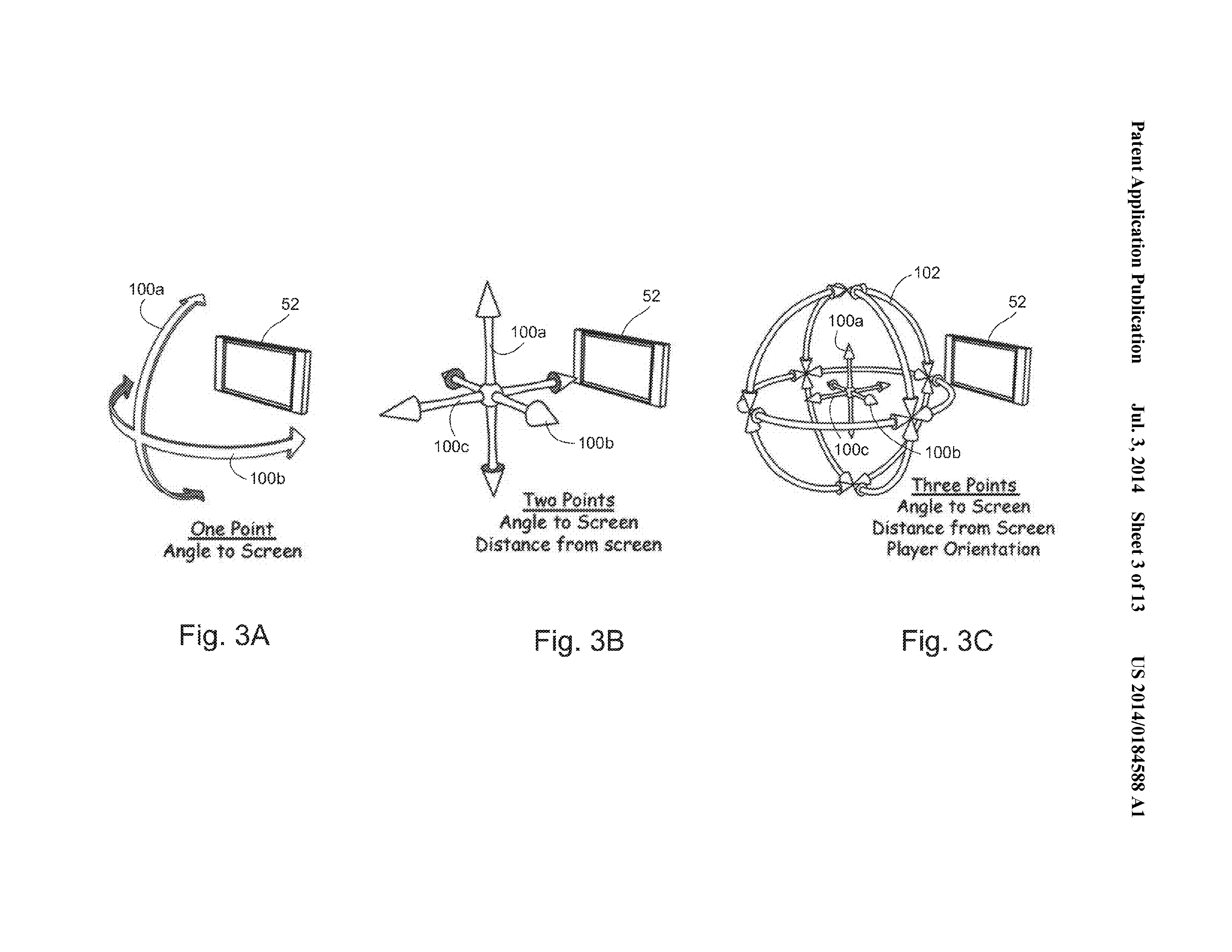
[0032] Number of Markers [0033] 1 point provides viewpoint movement along a spherical shell [0034] 2 markers provides position in 3D space of the viewpoint assuming eye is looking at the screen. [0035] >=3 points provide position in 3D space of the viewpoint as well as eye viewing orientation. [0036] 1 point provides the greatest physical presence as player normally moves head side to side to view an object or scene to understand the spatial structure. [0037] 2 point adds the ability to move viewpoint closer or further from the display assuming the eye remain looking at the display (reasonable assumption) [0038] 3 points provide viewpoint orientation. Game can become aware of player's viewing direction (e.g. other game characters might say "hey look at me")
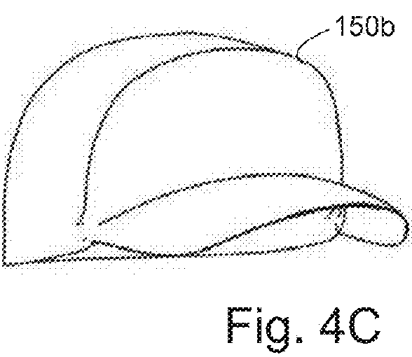
[0039] Wearable Mount [0040] Hat [0041] Headband [0042] Glasses [0043] Anything wearable on head or even other part of the body represents possible mounting opportunity
[0044] Options [0045] Camera on head, marker on TV [0046] Multiple cameras to divide field of view
[0047] Other Tracking Technologies [0048] Magnetic [0049] Ultrasonic
Example Usage
[0050] Viewing:
[0051] The illusion of physical presence
[0052] Players natural movement as viewing input
[0053] Dodging
Game Character Awareness
[0054] E.g. Game character becoming aware when the player looks away
Physical Presence Visual Enhancement
[0055] These techniques maximize the 3D object's physical presence illusion: [0056] View point change results in view frustum change [0057] Objects modeled in real world coordinates and placed near the physical TV screen [0058] Increase parallax--introduce near field and far field objects in view to maximize parallax motion [0059] Enhance movement by scaling and offsets of marked points or marker placement [0060] 3D data can be modeled in real world space coordinates (e.g., a 3D character such as a football player can be 15'' tall placed near the plane of the display) [0061] As user eye position moves, appropriately rotate and translate in 3D characters to match the proper viewing from new eye position
And of course the imagery:


[0085] FIGS. 4A-4C show different non-limiting options for devices that can be worn on the head and can support a marker or emitter for tracking purposes. Such devices can include for example a hat, a headband, glasses, or anything that is wearable or supportable on the head or other part of the body to provide possible mounting opportunities. For camera based tracking, it is possible for example to wear a marker 56b on the head and provide a camera 56a in a stationary position such as on the display 52. A visible band light camera can be used in conjunction with face detection software to determine the location of the head and to extrapolate the position of the eyes. To improve detection, it is possible to decrease the signal-to-noise ratio by wearing a marker. In the case of an IR camera, the infrared spectrum detection can be enhanced by ignoring all visible spectrum. Infrared (IR) emitters such as IR LEDs can be used to illuminate a scene with retroreflector markers. An IR emitter can be worn directly as markers providing high signal-to-noise ratio. Other arrangements can include a camera on the player's head and a marker on the display 52 or other fixed location in the room, or multiple cameras or other imaging devices to divide the field of view. Ultrasonic, magnetic, electromagnetic or any other suitable tracking technology can be used.


BRIEF DESCRIPTION OF THE DRAWINGS
[0062] These and other features and advantages will be better and more completely understood by referring to the following detailed description of exemplary non-limiting illustrative embodiments in conjunction with the drawings of which:
[0063] FIG. 1 schematically shows an example non-limiting graphics display system including user tracking;
[0064] FIGS. 2A and 2B illustrate different example non-limiting tracking types;
[0065] FIGS. 3A-3C further illustrate example non-limiting tracking types;
[0066] FIGS. 4A-4C illustrate example non-limiting headgear for tracking head position and movement;
[0067] FIGS. 5A-5C show example viewing frustum in front of a subject's eyes for different viewing directions;
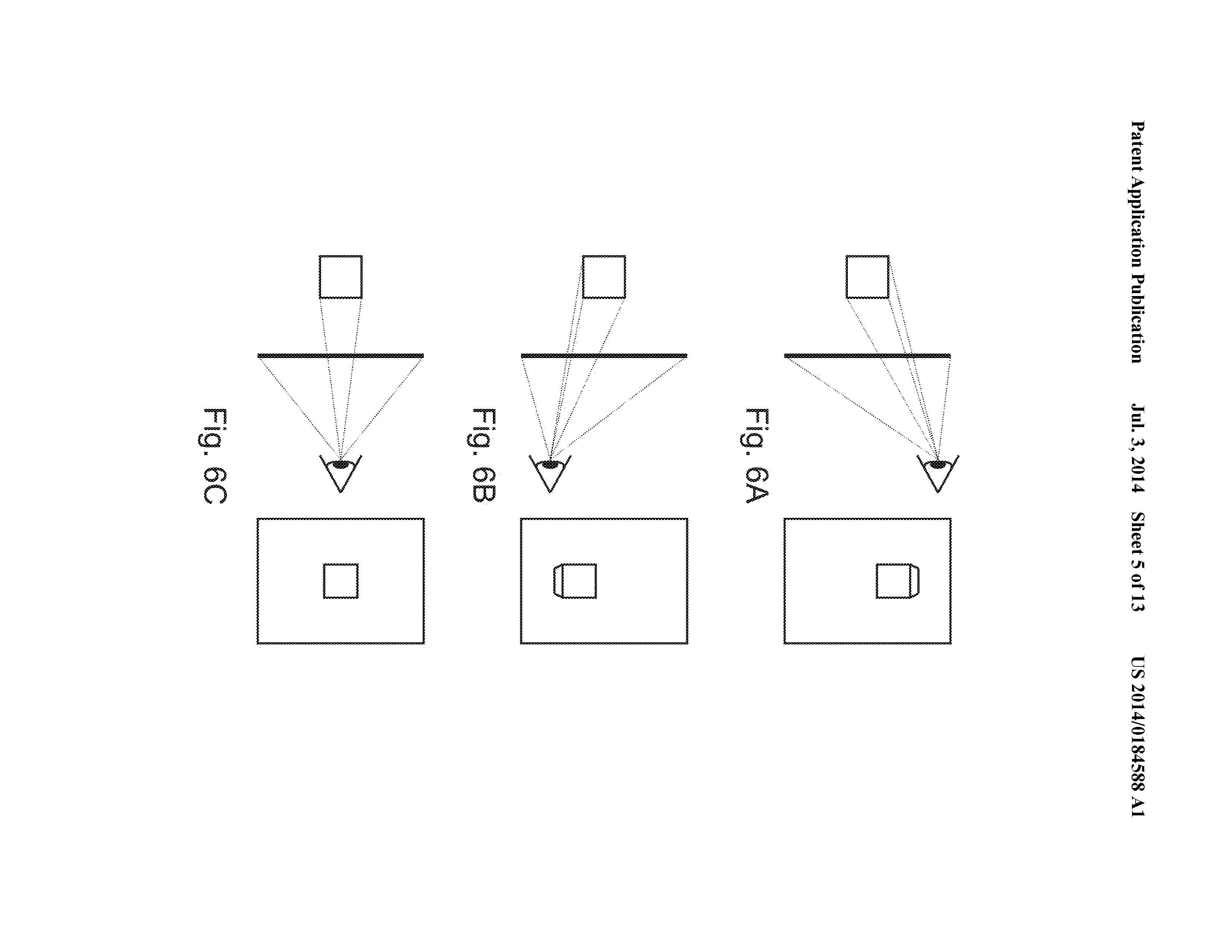
[0068] FIGS. 6A-6C show example graphics perspectives;
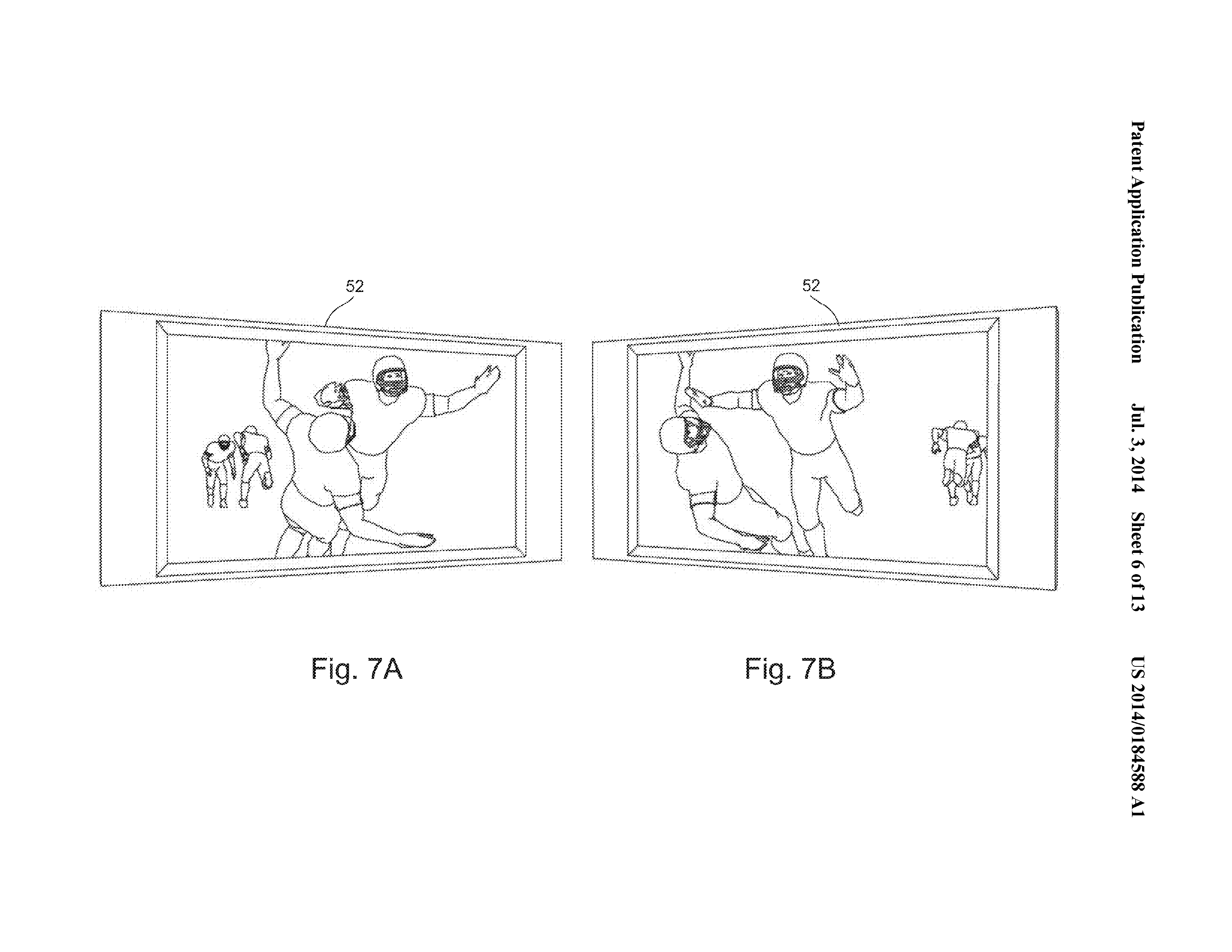
[0069] FIGS. 7A-7B show example images without 3-D enhancement but with parallax effects;
[0070] FIGS. 8A-8C show example images with 3-D enhancement;
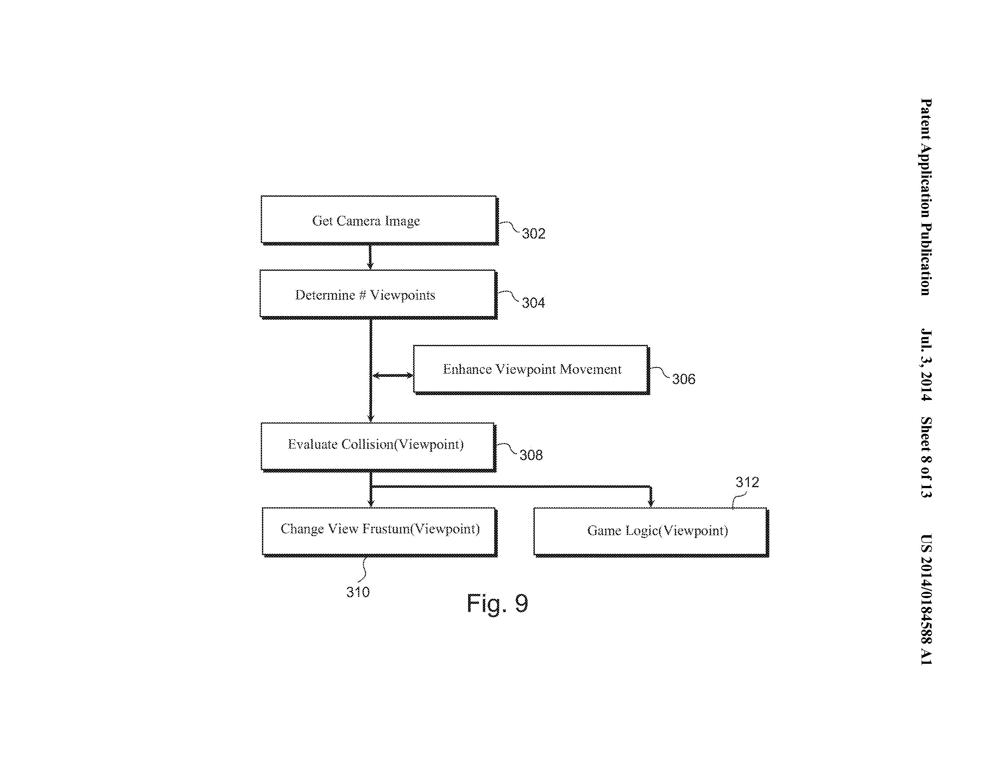
[0071] FIG. 9 shows an example non-limiting software processing algorithm;
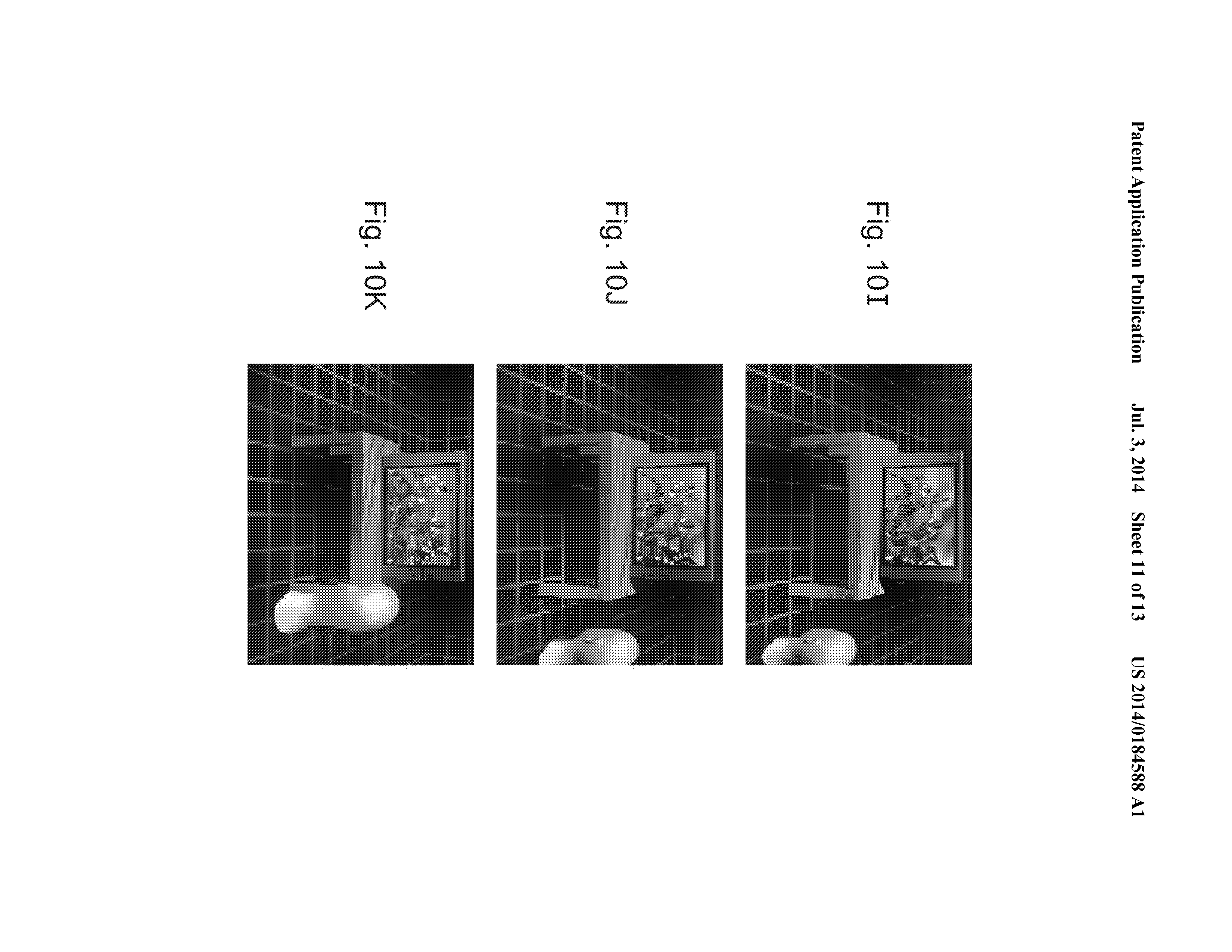
[0072] FIGS. 10A-10K show example third person images based on different head positions; and
[0073] FIGS. 11A-11H show additional first person example non-limiting 3-D enhanced images.
Detailed descriptions for each of these are available at the link. I posted the detailed description for figures 4A-4C above under the related image. However, there is a very interesting section at the end of the document, with further example enhancements this invention can bring. I bolded the enhancements I find most peculiar.
Source: http://appft.uspto.gov/netacgi/nph-...s1=Nintendo.AS.&OS=AN/Nintendo&RS=AN/Nintendo[0095] Further example enhancements:
[0096] Augmented Reality. Some synthetic picture intermixed with the real world can be used. This is a quick and realistic possibility to e.g., project certain types of images such as robots or to play a chess game. If we can locate in the real world where a planar surface is, we could each look through this object and see the same virtual object augmented into the real world. A display that is 50% real world, 50% synthetic, with positioning techniques and way to possibly detect motion or position is possible.
[0097] It is possible to use goggles to accommodate eye glasses. If used, then it is possible to handle see-through. An alternative is to capture the real world with a camera. Resolution is less, but we get the benefit of providing a hyper stereo view and enhancement of real world view.
[0098] It is possible to Invite your Curiosity by displaying the "inside" image on a screen that everyone could see. One way: cupped mirror could be half-reflective, one-way so observers can see an image of what the user is seeing. This gets a larger group involvement. Another way is to provide multiple head sets.
[0099] Enhancing the VR experience Additional output devices that enhance the experience can be provided. For example, we can put light out that is correlated to the image to provide "ultra wide field of view correlated lighting." Given that your eye does not see clearly in the periphery, this could still be useful and interesting.
[0100] Additionally, smell is a very strong sense. There may be some ways to produce aromas for a very strong experience.
[0101] Virtual wind could enhance the experience.
[0102] Temperature: blowing cool air on your face.
[0103] Physiologically comfortable stereo viewing is a way to prevent headaches. If you find a little spec on your windshield, focus on that and then far field and then back again. Eye strain happens quite quickly. Lots of folks in the past require the users to focus far field and close up, but this can cause headaches. We can stay on one side of the focal point cone, to provide higher level of comfort.
[0104] Detect Emotions via monitoring mental state. Brain wave detection, detect eye movement, heart rate monitor or the like can be used. If we provide goggles, we can also provide detectors (electrodes) fairly easily.
[0105] Shroud Possible to filtering out the real world by using a shroud
[0106] While the technology herein has been described in connection with exemplary illustrative non-limiting embodiments, the invention is not to be limited by the disclosure. The invention is intended to be defined by the claims and to cover all corresponding and equivalent arrangements whether or not specifically disclosed herein.
If link doesn't work, just search the application number here.