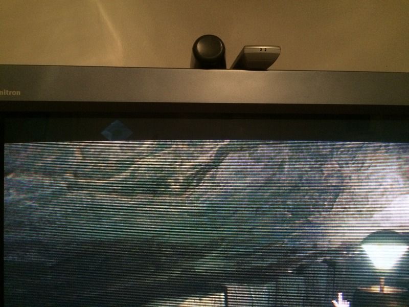
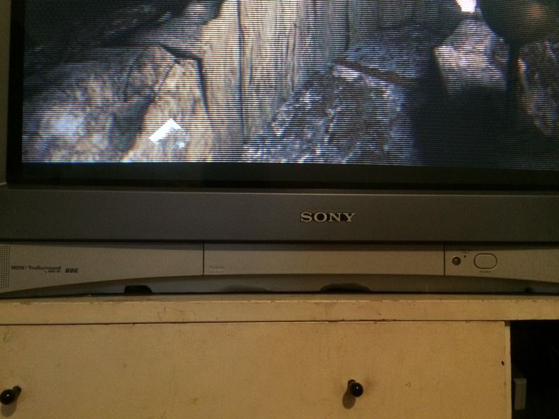
I have this plan to build a retro multicade cabinet using a Sony KV-32FV310 and have some questions about repair/refurbishing a CRT. First of all the picture seems to have bowing at the top and bottom that I tried to capture:
Those scan lines are impressive though aren't they? Images are from Riven PS1 disc being played on a PS2 connected via component. Any way, so there is the bowing problem, and in general I wanted to "go over" the TV before going to the trouble of putting it in a big setup. I wanted to replace anything I could, such as capacitors or resistors etc., calibrate it as thoroughly as I can, and anything else that would both prolong it's life and improve the image the best it can be.
My question is, should I try and tackle this on my own or take it to an electronics repair place? And if the answer is on my own, does any one have some resources for getting started? I have some engineer friends and we were just going to start taking it apart and checking it out and looking at the caps and things and go from there seeing if we could find replacements, find the pots to mess with the image, etc. Lastly, if I was going to take it to a repair place, do you think they would be able to do what I want with it or would they just give it a quick look and say it's good enough? As you all should understand, my goal is not to have a "working" set but to get it to the best it can be, even if it costs a little extra.
P.S. - PS3 via component @480i looked pretty bad. I was surprised, especially during motion. We were playing "The Cave."
Watch the high-voltage circuit in the/a TV and esp. the leftover charges while
the TV is off! If you have no idea about it, don't touch the TV in any way
from the inside, go to a TV engineer instead! You can get shocked to death or
get paralyzed! Big tubes run at a pretty high voltage, about 25kV! Don't mess
with it! Having said that I would do as you say in replacing all the caps and
resistors because it will extend life of the tube and also can increase
picture quality again. However there is also a chance to mess up the signals
running through the circuits making the picture look worse in the end. Why?
Well, some of the TV circuits are pretty tight on the capacities etc. used. Due
to bad soldering, bad wiring etc. you may add additional parasite capacities
which will most often increase the total capacity of the given circuit. And
this can lead, for example, to a dumping of the high-frequencies of the signal
running across. Hence, a video signal may lose its higher frequencies and as
such the picture becomes less sharp. Usually one can't prevent such a
situation of not introducing some parasite capacities or some additional
induction unless you use original components and solder them like in the
factory. However, some circuits allow for more tolerance than others. But when
ever there is high-frequency in a circuit you can be rest assured that the
components are tightly designed with respect to each other. This may go as far
as not being able to simply replace or even move a wire because of its
specific capacity and inductance under high-frequency which could be part of
the design process with respect to all other components of the circuit in
question. Sounds difficult, but not so much for an TV engineer/technician
because (s)he has something more on the table and a skill which isn't easy to
acquire, i.e. being able to use an oscilloscope while being able to
re-tuning/balancing the circuit after having installed all the new components.
And this re-tuning is the most difficult part because you literally need to
understand how each component works (esp. under high-frequency). And you also
need to know how the circuits in a TV are supposed work to judge the curves
seen on the oscilloscope. That's what you pay for. And it's well spent!
I hope I haven't smashed your enthusiasm. Well, if you are not that skilled
yet want to proceed, try to start with one of these old
small/mini/pocket/mobile/camping TVs. Use the smallest one you can get,
because they will run on a lower high-voltage, about 5kV to 10kV (still
dangerous, mind you!), and are easy to deal with. A good exercise is to
entirely decompose and desolder the whole tube and later compose and solder it
together again seeing if you get the same (if any xD) picture. If this works,
you may replace parts with new ones and may also start to measure if the new
component produces a similar/better characteristic -- while getting more and
more familiar with the circuit and its peculiarities. If you can handle it,
you may try one of the big guns.


